#4 – 20133 102nd Avenue, Langley, B.C. V1M 4B4 Canada

#4 – 20133 102nd Avenue, Langley, B.C. V1M 4B4 Canada
In 2026, global buyers are evaluating Stamped Contact Spring designs with greater attention to reliability, miniaturization, and supply continuity. These components may look modest, yet they control contact pressure inside switches, battery assemblies, connectors, sensors, and compact electronic modules. Small parts. High stakes.
Industry forecasts support this purchasing shift. MarketsandMarkets’ recent connector market analysis identifies rising demand from automotive electronics, telecommunications, industrial controls, and consumer devices. Grand View Research also reports continued expansion in the global electrical and electronic connectors market, supported by vehicle electrification and higher device density. These trends increase pressure on spring suppliers to deliver consistent force, corrosion resistance, and stable electrical performance.
For buyers, the main question is not simply which spring costs less. It is whether the chosen type maintains contact after repeated compression, vibration, heat exposure, and surface contamination. Common options include flat stamped springs, cantilever contact springs, battery contact springs, grounding springs, and custom multi-point designs. Each geometry creates different force curves and installation requirements.
Material selection requires equal care. Stainless steel, copper alloys, and nickel-plated grades can behave differently under temperature cycling and current load. A supplier’s tooling experience also matters, especially when burr control and dimensional repeatability affect assembly yield. Fit matters.
This guide compares the leading Stamped Contact Spring types for global buyers in 2026. It uses practical selection criteria, manufacturing considerations, and published market research. Some supplier claims still deserve closer verification. Real performance depends on testing, not attractive specifications alone.
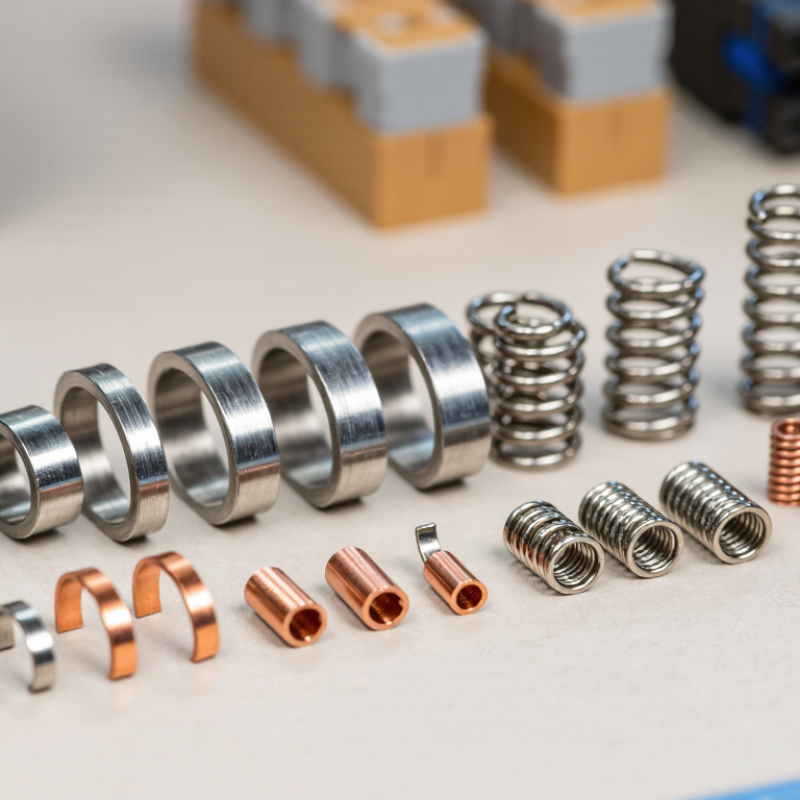
Stamped contact springs are compact electrical components formed from flat metal strip. A press cuts and bends the material into a controlled spring profile. They provide pressure, electrical continuity, or both inside connectors, switches, battery contacts, and sensor assemblies.
Their structure usually includes a mounting base, flexible beam, contact crown, and terminal area. Small bends concentrate movement in the spring zone. The contact crown touches a mating surface, while the base holds alignment during assembly.
Copper alloys are common because they balance conductivity and resilience. Surface plating can improve corrosion resistance and reduce contact wear. Thickness, bend radius, and material temper strongly affect performance.
The operating principle is simple. When compressed, the spring stores elastic energy and pushes against the opposing contact. This force helps break through light surface films and maintain a stable current path during vibration.
Travel must remain within the elastic range. Excessive compression can cause permanent deformation. That mistake is easy to miss.
In practical design work, engineers check contact force, electrical resistance, insertion height, and cycle life. A spring may perform well in a sample but weaken after repeated loading. Manufacturing tolerance also matters. A few tenths of a millimeter can change the working force noticeably.
Testing should include dimensional inspection, compression cycling, temperature exposure, and vibration. Real assemblies often reveal problems that calculations overlook.
Stamped contact springs vary by load, travel, space, and current path.
Cantilever springs suit compact PCB connectors and battery contacts. Their long beam provides controlled deflection with moderate insertion force.
Dome springs deliver short, tactile movement in switches and keypads.
Wave springs offer repeated compression where vertical space is limited.
Multi-finger grounding springs support EMI shielding around covers, housings, and cable interfaces.
Application demands are becoming more severe.
The IEA Global EV Outlook 2025 reports that electric car sales exceeded 17 million in 2024. This growth increases demand for reliable stamped contacts in battery modules, charging equipment, and power-control units.
Automotive buyers should specify stable contact force, vibration resistance, and corrosion protection. IEC 60512 test methods can help evaluate electrical continuity, temperature rise, and mechanical endurance.
Still, test results may not predict every field condition. Real assembly tolerances often expose weaknesses.
Tips:
Match spring geometry to the expected travel, not only the available space.
Check force loss after repeated cycling.
Review plating thickness, burr control, and edge direction.
A flat spring may look economical, but it can fatigue when over-deflected.
Prototype with the actual mating material and housing.
This step is sometimes skipped, and that is a costly mistake.
Use stamped springs with clear drawings, controlled material data, and traceable inspection records.
For stamped contact springs, material selection begins with the required force, deflection, and operating temperature. Copper alloys provide strong conductivity and reliable forming performance. Phosphor bronze suits repeated movement and moderate spring stress. Beryllium copper offers higher strength, but manufacturing controls must be carefully reviewed. Stainless steel can resist corrosion, although its conductivity is lower.
Finish matters. Tin plating supports solderability and offers practical protection in many indoor assemblies. Silver provides excellent conductivity, but it may tarnish in sulfur-rich environments. Gold plating performs well at low signal levels and frequent mating points. Nickel often works as a diffusion barrier beneath the final finish. The plating thickness must match the contact load, wiping action, and expected service life.
Check the full contact system, not only the spring. A hard finish can increase wear on a mating surface. A soft finish may deform under repeated compression. In production reviews, engineers often find that surface contamination causes more failures than the selected alloy. Clean handling is essential. Test it.
Useful validation includes contact resistance, temperature cycling, humidity exposure, and repeated compression testing. A stamped edge can also create local stress or scrape through thin plating. This detail is easy to miss. I have seen designs pass initial checks, then lose stability after fretting cycles. That result deserves honest review, not a rushed material change. Dimensional tolerance, burr control, and plating adhesion should be confirmed with supplier inspection records and sample testing.
Material and surface-finish selection for contact reliability
The chart compares representative room-temperature electrical conductivity values for common stamped-contact spring base materials, expressed as % IACS. Copper alloys generally provide higher conductivity, while stainless steel provides greater resistance to deformation and is often selected for grounding or shielding springs. Gold plating is commonly used for low-level or low-mating-force signal contacts, tin plating for cost-sensitive power and battery contacts, and nickel plating where wear resistance and environmental durability are priorities. Actual reliability depends on alloy temper, contact force, plating thickness, mating materials, temperature, and contamination.
When global buyers compare stamped contact spring designs, electrical stability matters as much as initial price. Common options include flat leaf, cantilever, U-shaped, and multi-finger springs. Each design controls contact force, travel, and package height differently.
A flat leaf suits compact interfaces with moderate movement. A cantilever spring can provide longer wiping action during mating. U-shaped forms offer useful compliance, but they may occupy more vertical space. Multi-finger designs distribute force across several contact points. They also demand tighter stamping control.
Performance testing should begin with normal force at the specified working displacement. Ask for force-deflection curves, not one attractive force value. Contact resistance should be measured before and after repeated mating cycles.
Humidity, vibration, and thermal cycling can reveal failures hidden in laboratory conditions. Inspect burrs, cracks, plating coverage, and spring-back after forming.
Edge quality matters. A small burr can damage a mating surface or create unstable resistance. Material selection should match temperature, fatigue, conductivity, and corrosion exposure.
Traceable material certificates and controlled process records support reliable purchasing across regions.
Buyers should compare tolerance stacks, tooling life, and inspection methods with the quoted unit cost. A low price can change quickly after tooling adjustments or field returns. Ask how samples represent mass production. This question is often neglected.
I would also request cross-section images from stamped samples, because surface appearance alone can mislead. Design reviews should include assembly force, retention, and accidental over-compression.
Excessive force may accelerate wear and increase connector damage. Some specifications remain uncertain until real assemblies are tested. That is where careful buyers learn the most.
2026 Top Stamped Contact Spring Types for Global Buyers
Stamped contact springs include cantilever beams, dome springs, multi-finger contacts, and compact battery terminals. Each type suits a different space, force, and current requirement. Manufacturing begins with stable strip material, controlled stamping dies, and clear dimensional tolerances. Common materials include copper alloys, stainless steel, and nickel-based options. Material certificates and lot traceability should remain available throughout production.
Customization may involve spring height, contact geometry, plating thickness, insertion force, and mounting features. Engineers should review the complete force-displacement curve, not only the free height. Small bends can change electrical stability. That detail is easy to miss. Applicable regional requirements should also guide material selection, surface treatment, and restricted-substance controls. A drawing alone is not enough.
Tips: Request first-article samples before mass production. Check burrs under magnification, especially near the contact tip. Measure plating thickness at high-wear areas. Use a calibrated force tester for compression and recovery tests. Inspect contact resistance after repeated cycling, vibration, and temperature exposure. I have seen attractive prototypes fail after modest cycling because the spring temper was inconsistent. Inspection plans should define sampling levels, acceptance limits, and corrective-action records. Visual checks help, but they cannot replace measurable evidence. One practical improvement is adding a gauge for critical bends. It costs little, yet it can reveal tool wear earlier. Suppliers should also retain inspection data by production lot for reliable audits and future adjustments.
| Stamped Contact Spring Type | Typical Applications | Common Material Options | Typical Material Thickness | Contact and Spring Characteristics | Common Customization Parameters | Relevant Manufacturing Standards and References | Key Quality Inspection Factors |
|---|---|---|---|---|---|---|---|
| Cantilever Contact Spring | Board-to-board connectors, signal contacts, switches, and compact electrical assemblies. | Phosphor bronze Beryllium copper Stainless steel | 0.10–0.80 mm | Provides controlled normal force through beam deflection. The free length, width, thickness, and bend radius strongly affect force and fatigue life. | Beam length, contact tip geometry, pre-load, bend angle, contact radius, plating, carrier design, and insertion-force target. | Material specifications may reference ASTM B194 for copper-beryllium strip, ASTM A666 for austenitic stainless steel, ISO 2768 for general tolerances, and IEC 60512 for connector test methods where applicable. | Free height, beam angle, contact force at specified deflection, permanent set, burr height, dimensional profile, plating thickness, and electrical resistance. |
| U-Shaped Clip Spring | Battery contacts, wire terminals, removable modules, and retention contacts. | Phosphor bronze Spring brass Stainless steel | 0.15–1.00 mm | Generates clamping force from two opposing legs. It can provide both electrical continuity and mechanical retention. | Clip opening, leg length, inside radius, retention force, contact dimple, mounting hole, slot, and anti-overstress stop. | Applicable material standards can include ASTM B139/B139M for phosphor bronze products and ASTM A666 for stainless steel strip. Product-specific electrical tests may use IEC 60512 methods. | Opening width, closing force, insertion and extraction force, leg symmetry, crack inspection at bends, burrs, coating adhesion, and resistance after cycling. |
| Flat Leaf Contact Spring | Relays, low-profile connectors, membrane switch assemblies, sensor modules, and grounding contacts. | Copper alloy Phosphor bronze Stainless steel | 0.08–0.60 mm | Offers a low-profile spring path with relatively predictable force over a limited deflection range. | Leaf length, width, offset, embossment, contact pad, relief slots, mounting features, and force-deflection profile. | ISO 2768 may be used for general dimensional tolerances when specified. Copper-alloy and stainless-steel material certificates should identify grade, temper, and thickness. | Flatness, profile, offset height, contact force, contact resistance, edge condition, surface finish, material temper, and visual defects. |
| Bifurcated Contact Spring | Signal connectors, relays, instrumentation sockets, and applications requiring contact redundancy. | Beryllium copper Phosphor bronze Nickel alloy | 0.10–0.50 mm | Uses two contact beams to improve redundancy and reduce the effect of localized contamination or surface irregularities. | Beam separation, twin-tip geometry, contact force, bridge width, insertion profile, plating system, and retention features. | ASTM B194 may be referenced for copper-beryllium strip. IEC 60512 electrical and mechanical test methods may be selected according to connector design requirements. | Beam-to-beam alignment, individual contact force, tip height, contact resistance, plating coverage, fatigue cycling, and short-circuit risk between beams. |
| Dome or Button Contact Spring | Keypads, tactile switches, control panels, consumer interfaces, and low-travel switching devices. | Stainless steel Nickel-plated steel Copper alloy | 0.05–0.30 mm | Produces a snap action or tactile response when the dome changes state under applied load. | Dome diameter, height, crown radius, operating force, travel, snap ratio, electrical path, and adhesive or carrier interface. | Stainless-steel material may be specified to ASTM A666. Switch performance can be verified using customer-defined force-travel and life-cycle requirements. | Operating force, return force, travel, snap ratio, dome height, concentricity, contact resistance, fatigue life, and surface cleanliness. |
| Battery Contact Spring | Battery holders, portable electronics, medical devices, toys, meters, and backup-power assemblies. | Nickel-plated steel Stainless steel Phosphor bronze | 0.20–0.80 mm | Combines spring deflection with stable electrical contact under battery insertion, vibration, and repeated replacement. | Battery diameter, polarity geometry, contact pressure, terminal height, anti-reverse features, weld tabs, plating, and housing interface. | Material and plating certificates should identify substrate, coating, thickness, and corrosion requirements. ASTM B117 may be used for comparative salt-spray evaluation when specified. | Contact force, battery retention, polarity position, terminal height, weld strength, contact resistance, corrosion resistance, and cycle durability. |
| Grounding and Shielding Finger Spring | EMI shielding, chassis grounding, enclosure seams, cable shields, and rack-mounted electronic equipment. | Beryllium copper Stainless steel Copper alloy | 0.10–0.50 mm | Provides multiple low-resistance contact points while accommodating dimensional variation between mating metal surfaces. | Finger length, pitch, contact height, mounting method, shield coverage, spring force, plating, and compression range. | ASTM B194 can be used for copper-beryllium strip. Shielding effectiveness and grounding performance should be validated in the final enclosure design. | Contact height, compression force, continuity, plating coverage, spring recovery, edge sharpness, mounting retention, and resistance after environmental exposure. |
| Wave or Corrugated Contact Spring | Multi-point grounding, connector compensation, battery systems, and assemblies requiring tolerance take-up. | Stainless steel Phosphor bronze Copper alloy | 0.15–0.80 mm | Uses repeated wave geometry to provide distributed force, vibration tolerance, and relatively long working travel. | Wave pitch, amplitude, number of waves, overall length, end configuration, force range, mounting holes, and surface treatment. | ASTM A666 is commonly referenced for stainless-steel strip. General tolerances, coating specifications, and test procedures should be defined on the drawing or purchase specification. | Wave height, pitch, overall length, force-deflection curve, permanent deformation, surface cracks, burrs, contact resistance, and repeatability. |
| Retaining and Locking Contact Spring | Connector locks, fuse clips, terminal retention, cartridge holders, and serviceable electrical modules. | Spring steel Stainless steel Phosphor bronze | 0.20–1.20 mm | Maintains component position while allowing controlled insertion, removal, or release during service. | Locking tab height, release force, retention force, engagement angle, hole pattern, anti-rotation feature, and wear-resistant coating. | ASTM A684 may be considered for carbon spring steel strip and ASTM A666 for stainless steel strip, subject to the selected grade and temper. | Retention force, release force, tab position, wear after cycling, fatigue cracks, dimensional stability, burrs, and coating adhesion. |
| Multi-Point Contact Bridge | Busbar interfaces, power distribution modules, grounding plates, and high-reliability low-voltage connections. | Copper alloy Copper Stainless steel with conductive plating | 0.30–1.50 mm | Uses several stamped contact points to distribute current and compensate for surface or assembly variation. | Number of contact points, bridge width, current rating, contact pressure, terminal geometry, heat-management features, and plating system. | Material standards may reference ASTM B122/B122M for copper plate, sheet, and strip or an equivalent national material specification. Electrical performance must be validated for the final current and temperature range. | Current-carrying resistance, temperature rise, contact force, flatness, dimensional profile, plating thickness, thermal cycling, and surface oxidation. |
Note: Thickness, force, tolerance, plating, and service-life values are typical engineering ranges rather than universal limits. Final requirements should be confirmed through the approved drawing, material certificate, application conditions, and product-specific validation plan.