#4 – 20133 102nd Avenue, Langley, B.C. V1M 4B4 Canada

#4 – 20133 102nd Avenue, Langley, B.C. V1M 4B4 Canada
Choosing the right medium voltage drive begins with the motor, but it should never end there. The International Energy Agency reports that electric motor systems consume about half of global electricity. In industrial facilities, the U.S. Department of Energy estimates that motor-driven equipment uses roughly 70% of electricity. These figures make efficiency important, but efficiency alone can mislead. A drive that performs well in a laboratory may struggle beside a dusty conveyor, a fluctuating pump, or a hot kiln.
Dr. Michael Brambley, a recognized motor-systems researcher at Pacific Northwest National Laboratory, offers a useful principle: “A motor system must be evaluated as a whole, not by isolated components.” That idea should guide every medium voltage drive comparison. Examine the load profile, starting torque, speed range, harmonic performance, cooling method, bypass arrangement, and maintenance access. Check the real operating hours, not only the nameplate rating. A 6.6 kV drive serving a large pump may reduce throttling losses, yet poor control settings can erase part of that benefit. Small details matter.
Reliability also deserves a physical test. Open the cabinet. Study the air path, cable termination space, protection scheme, and replacement procedure. Ask how quickly technicians can restore service after a cell failure. Independent reports often present attractive market growth and efficiency claims, but site conditions remain less tidy. This is the uncomfortable part. No selection method is perfect. The best choice is the one supported by measured data, transparent lifecycle costs, and evidence from similar installations. That is where professional judgment begins.
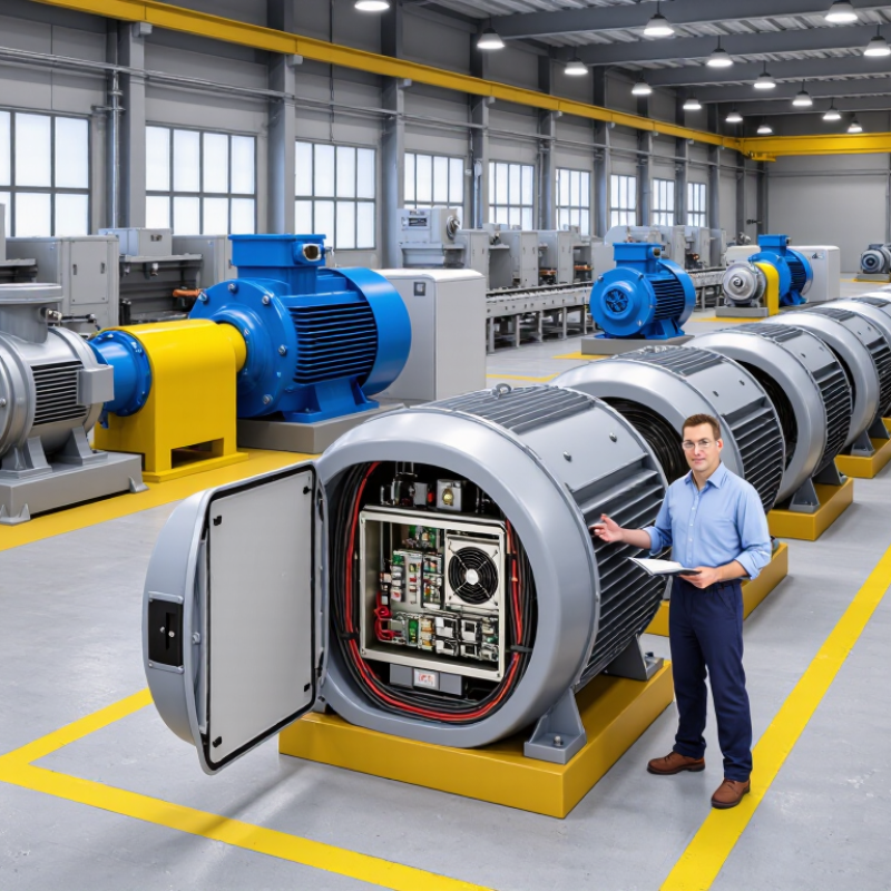
Medium voltage drives (MVDs) control motor speed and torque in demanding electrical systems. They are commonly used with pumps, fans, compressors, conveyors, crushers, and large cooling systems. These drives reduce starting stress and improve process control. In water treatment, a drive may regulate pump flow as demand changes. In mining, it can soften acceleration on long conveyors. The right application matters more than a fashionable specification. That is easy to overlook.
Choosing a drive starts with the motor and the driven load. Confirm voltage, rated power, current, speed range, overload profile, and starting frequency. A pump often needs different control behavior than a crusher. Check harmonics, short-circuit levels, enclosure rating, cooling method, and applicable electrical standards. Site temperature and dust can affect reliability. I have seen projects focus on efficiency while ignoring cable length and heat removal. That mistake can become expensive.
Tips: Map the load cycle over a full shift, not only at peak output. Ask whether bypass operation is required during maintenance. Review protection, isolation, grounding, and emergency-stop coordination with qualified engineers. Keep space for filters, ventilation, and safe access. Request test records and clear service procedures. Do not trust a perfect datasheet alone. Field conditions are messier. A pilot test may expose resonance, unstable control, or unexpected harmonics before installation. Let operators review the controls; they notice practical problems early.
Choosing the best medium voltage drive starts with the motor, not the drive cabinet. Check the motor’s rated voltage, full-load current, speed range, insulation system, and starting torque. A 3,300-volt motor may require different protection from a 6,600-volt motor. Confirm compatibility with the motor manufacturer’s data and recent test records. Do not rely on the nameplate alone.
Study the load across its full operating cycle. Pumps often need steady torque, while crushers and conveyors may demand high torque during acceleration. Record starts per hour, acceleration time, overload duration, and braking needs. Also consider altitude, dust, heat, and cabinet ventilation. A drive that performs well in a clean test room may struggle beside a hot process line. Harmonic limits and power-factor requirements should be reviewed with the site electrical engineer.
Tips: Measure real operating current before selecting the drive. Leave practical thermal margin, but avoid excessive oversizing, which can increase cost and reduce control efficiency. Check bypass arrangements, emergency stopping, maintenance access, and spare-part availability. A spreadsheet helps, but it can hide poor assumptions. Review actual production trends with operators. Their observations often reveal short torque spikes that calculations miss. Even experienced teams can overlook cable length or motor insulation stress; a final engineering review is worth the time.
Assess the motor rating, load profile, available voltage, and operating requirements before selecting a medium voltage drive.
The chart shows the estimated full-load current of a 5 MW, three-phase motor at common medium-voltage levels. Values use a power factor of 0.90 and motor efficiency of 96%, calculated with I = P ÷ (√3 × V × power factor × efficiency). Higher voltage reduces motor and drive current, which can lower cable size and distribution losses. Final selection should also verify variable-torque or constant-torque load behavior, required speed range, starting torque, overload capacity, harmonic limits, cooling conditions, and bypass or regenerative operation.
Selecting a medium voltage drive begins with the load, not the catalog. The IEA’s Energy Efficiency 2023 report estimates that electric motor systems consume about half of global electricity. Small efficiency gains therefore matter. For pumps and fans, a voltage-source inverter with a two-level or multilevel topology can provide practical speed control. Multilevel designs usually reduce output voltage steps and motor stress. They may also increase cabinet complexity. Choose the compromise carefully.
Check voltage, current, overload, and short-circuit ratings against the real operating profile. A 3.3 kV drive may not suit a motor with frequent starts or high-breakaway torque. Review continuous and one-minute overload ratings, not only horsepower. The U.S. Department of Energy reports that motor systems consume roughly 70% of industrial electricity. Poor sizing can create avoidable losses. It happens more often than expected.
Control features should match process risk. Sensorless vector control may work for steady conveyors, while encoder feedback can improve low-speed torque. Regenerative braking deserves attention on downhill conveyors and hoists. Harmonic performance must align with IEEE 519 limits at the point of common coupling. Confirm motor insulation, cable length, bypass arrangements, enclosure rating, and cooling method. IEC 61800-3 compatibility checks are useful here. In field reviews, documentation is often the weak link. A technically sound drive can still fail integration when protection settings, communication protocols, or grounding details remain unclear. Building a test plan around actual load data is safer than trusting nominal ratings.
Choosing the best medium-voltage drive starts with the load, not the brochure. In field assessments, pump speed changes often reveal more savings than motor nameplate efficiency. The U.S. Department of Energy’s 2022 Motor Systems Market Assessment estimates that motor-driven equipment uses about 69% of electricity in U.S. manufacturing. Small efficiency losses therefore become expensive. Compare weighted efficiency across the full operating profile. IEC 61800-9-2 offers a practical framework for evaluating drive-system efficiency classes.
Harmonics deserve measured attention. IEEE 519-2022 defines distortion objectives at the point of common coupling, not only inside the drive. Request a power-quality study, transformer impedance, and total demand distortion. A passive filter can solve one problem and create another resonance. That risk is easy to miss. Reliability also depends on cooling, thermal margins, fault logging, and spare modules. Ask for mean time between failures, test conditions, and service-response data. MTBF without conditions is weak evidence.
Safety must include isolation, grounding, arc-flash boundaries, and controlled access. NFPA 70E emphasizes electrically safe work practices and risk assessment, while local regulations remain decisive. During commissioning, verify discharge times, interlocks, and emergency-stop behavior. Maintenance teams need clear diagnostics, inspection points, and replaceable cooling fans. Remote monitoring helps, but it cannot replace a trained walkdown. A drive may look efficient and still be difficult to maintain. Five-year cost models should include downtime, harmonic mitigation, spares, training, and inspections. The best choice may be less efficient on paper. It may be safer and more available.
How to Choose the Best Medium Voltage Drive
Selecting the best medium voltage drive requires more than comparing purchase prices. Total cost analysis should include engineering, installation, energy, maintenance, downtime, and disposal. The International Energy Agency reports that electric motor systems consume about 46% of global electricity. Even modest efficiency gains deserve careful attention.
Consider a 6.6 kV pump operating 4,000 hours annually. A one-percent efficiency difference at 1 MW represents roughly 40 MWh of yearly energy. That figure is simple. The plant is not. Load variation, harmonic filtering, cooling systems, and motor compatibility can change the result. IEC 61800-9-2 provides a useful framework for evaluating drive-system efficiency, rather than judging the converter alone.
Maintenance data should be realistic. Include spare-part availability, technician training, inspection intervals, and the financial impact of an unexpected stoppage. The U.S. Department of Energy identifies motor systems as a major share of industrial electricity use, reinforcing the value of operational data. Still, a lifecycle model can mislead when it uses a perfect load profile. Real pumps surge. Fans run below design speed. Production schedules change.
Use measured power data when possible. Compare at least three operating scenarios, including reduced-load operation and a failed-drive event. Energy savings matter, but so do stable control, safe access, and recovery time. The cheapest drive may win the quotation. It may not win the plant.
| Evaluation Dimension | Configuration A Standard air-cooled drive | Configuration B High-efficiency air-cooled drive | Configuration C Liquid-cooled drive | Configuration D Regenerative drive system |
|---|---|---|---|---|
| Typical motor voltage range | 2.3–6.6 kV | 2.3–6.6 kV | 3.3–11 kV | 2.3–6.6 kV |
| Typical power range | 2–10 MW | 2–15 MW | 5–30 MW | 2–15 MW |
| Primary application fit | Fans, pumps and conveyors with moderate duty cycles | Continuous-process fans, pumps and compressors | High-power, high-load or high-ambient-temperature applications | Cranes, test stands, hoists and applications requiring braking energy recovery |
| Expected drive efficiency at rated load | 97.0–98.0% | 98.0–98.8% | 98.2–99.0% | 97.5–98.5% |
| Typical input power factor | 0.95–0.98 | 0.96–0.99 | 0.96–0.99 | 0.95–0.99 |
| Cooling requirement | Filtered plant air; clean environment preferred | Filtered plant air with improved thermal management | Closed-loop water or water-glycol cooling system | Filtered plant air; braking equipment may require additional cooling |
| Approximate heat loss at 5 MW output | 100–150 kW | 60–100 kW | 50–90 kW | 75–125 kW |
| Initial equipment cost index | 100 | 110–125 | 125–150 | 135–165 |
| Installation and auxiliary-system complexity | Low to medium | Medium | High; requires cooling-water infrastructure | High; requires regenerative energy path and protection coordination |
| Routine maintenance frequency | Semiannual inspection; filters and fans require attention | Annual inspection; reduced airflow-related maintenance | Annual inspection; cooling loop and heat exchanger checks required | Semiannual inspection; braking and regenerative components require additional checks |
| Expected service life with proper maintenance | 15–20 years | 15–20 years | 15–25 years | 15–20 years |
| Energy-cost exposure over 20 years | High for continuously operated loads | Medium to low | Lowest where operating hours and load factor are high | Medium; energy recovery can reduce net consumption during braking |
| Suitability for variable-speed energy savings | Good for centrifugal loads | Excellent for continuous centrifugal loads | Excellent for high-power continuous loads | Good where acceleration and braking are frequent |
| Lifecycle risk profile | Higher sensitivity to dust, blocked filters and ambient temperature | Balanced risk and efficiency profile | Cooling-system dependency and water-quality risk | More complex protection, harmonics and energy-flow coordination |
| Best selection condition | Lowest initial cost is the main priority and operating hours are limited | Balanced total cost, high availability and continuous operation are required | High power density, hot environments or restricted room ventilation dominate the decision | Braking energy is substantial and can be returned to the electrical network |