#4 – 20133 102nd Avenue, Langley, B.C. V1M 4B4 Canada

#4 – 20133 102nd Avenue, Langley, B.C. V1M 4B4 Canada
Choosing rapid prototyping injection molding is not simply a race for the lowest tooling price. It is a decision about risk, timing, material behavior, and production intent. A prototype mold may look simple on a quotation, yet small details can change its value. Steel selection, gate location, cooling layout, draft angles, and expected shot count all matter. One overlooked rib can create sink marks, warpage, or difficult ejection.
John Bozzelli, a respected injection-molding consultant, states, “The mold is the heart of the injection molding process.” That principle should guide every supplier discussion. A reliable partner will review the CAD model, question unclear tolerances, and explain realistic cycle times. They should also show how the chosen resin behaves under heat, pressure, and repeated molding. Ask for mold-flow feedback when the part has thin walls, deep ribs, or uneven thickness. Real evidence matters.
Speed still matters. But speed without verification can become expensive rework. Compare tool materials, sample approval steps, inspection methods, and design-change policies. Request sample parts, not only polished photographs. Hold them in your hand. Check flash around the parting line, visible weld lines, surface texture, and dimensional consistency. Some decisions remain uncertain until the first trial. That is normal, not failure. The important point is learning quickly and documenting each correction. This guide explains how to choose rapid prototyping injection molding with clearer technical judgment, stronger supplier communication, and fewer unpleasant surprises.
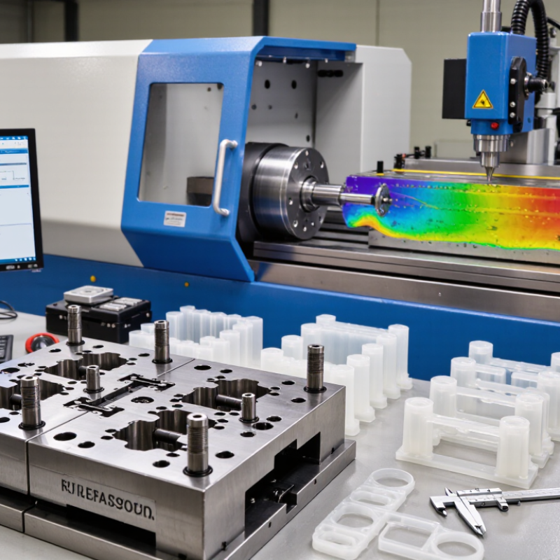
How to Choose Rapid Prototyping Injection Molding?
Define demand before discussing tooling. Prototype runs commonly stay under 10,000 units, but that number is not a fixed rule. A medical enclosure may need only 300 pieces for fit testing. A consumer part may require 8,000 units for field trials. Estimate your actual use, not an optimistic sales forecast. Ask how many samples are needed for testing, customer review, and replacement stock. I have seen teams order too many parts before confirming the design.
Part scope matters just as much. List the material, surface finish, color, wall thickness, and critical dimensions. A simple cover may suit a single-cavity mold with limited tooling features. A part with clips, deep ribs, or side holes may need slides or additional machining. These details affect lead time, mold cost, and repeatability. Keep the first design practical. Perfect is often expensive.
Request a written process plan. It should identify inspection points, expected tolerances, sampling quantity, and approval stages. Confirm whether the mold can support later revisions. This matters when prototypes reveal weak snap fits or sink marks. During one evaluation, a small draft change improved ejection but altered the visible surface. The lesson was uncomfortable: the CAD model was not finished. Under 10,000 units, flexibility usually has more value than maximum automation, though every project deserves its own calculation.
When speed matters, aluminum molds often offer a practical path for prototype injection molding. With a stable design, delivery may take about two to six weeks. That range is not guaranteed. Complex slides, tight tolerances, and late drawing changes can extend it. Aluminum machines quickly and usually costs less than hardened steel. It suits pilot runs, functional testing, and early market feedback. However, it may wear faster under high-volume production. Mold life depends on resin, part geometry, cycle settings, and maintenance.
Tips: Ask for a design-for-manufacturing review before machining starts. Confirm draft angles, wall thickness, gate locations, cooling access, and expected output. Request a clear timeline with design approval, tool fabrication, sampling, and final inspection. A short schedule can hide approval delays.
Experienced molding teams also check dimensional stability after the first samples. A part may fit correctly while its surface finish still needs adjustment. Small changes can affect shrinkage, warpage, or assembly performance. I have seen projects choose aluminum for speed, then regret ignoring future volume. That is a fair concern. If production demand is uncertain, compare aluminum’s lower entry cost with a steel tool’s longer service life. The best choice depends on test goals, annual quantity, material behavior, and tolerance requirements. Keep the decision evidence-based, not driven by the shortest promised date.
Choosing rapid prototyping injection molding starts with resin screening, not mold speed. Resin shrinkage can shift a 50 mm feature by several tenths of a millimeter. Near ±0.1 mm, that difference matters.
Review the resin’s datasheet for molding shrinkage, moisture sensitivity, flow behavior, and reinforcement content. Unfilled resins often shrink more uniformly. Glass-filled grades can improve stiffness, but fibers may create directional shrinkage and visible warpage. Dry hygroscopic materials carefully. A small moisture mistake can cause bubbles, brittle edges, or unstable dimensions.
Keep the geometry realistic. Thin ribs, deep pockets, and uneven wall thickness increase cooling differences. Use consistent walls where possible. Add draft before chasing tight tolerances. A nearly perfect CAD model may still produce a difficult molded part.
I once accepted a material based only on strength data. The first parts passed visual inspection but missed a critical hole position. The mold was not the only problem. Cooling time, gate location, and measurement temperature also affected the result. That mistake changed my process.
Build a small screening plan. Mold several samples, condition them, then measure key features with calibrated equipment. Record cavity number, molding temperature, cooling time, and part age. Compare results across the actual production direction. Measure twice.
Tolerance claims need context. A target near ±0.1 mm may be practical for selected features, but not every surface. Flatness, warpage, and assembly stack-up require separate checks. When results drift, adjust the process before modifying steel. Sometimes the resin choice is the real constraint.
How to Choose Rapid Prototyping Injection Molding?
Cycle time is a practical cost driver, not just a machine setting. Typical injection cycles run from 15 to 60 seconds. That equals roughly 240 to 60 cycles per hour. With a four-cavity mold, output may range from 960 to 240 parts hourly. The difference becomes significant during pilot production. A cycle includes filling, packing, cooling, mold opening, and ejection. Cooling often consumes the largest share. The Society of Plastics Engineers’ Injection Molding Handbook identifies cooling as a major timing factor because heat removal controls dimensional stability. Faster is not always better. A rushed cycle can create warpage, sink marks, or weak weld lines.
Estimate economics using machine time, labor, resin, scrap, and setup changes. The U.S. Department of Energy’s Industrial Assessment Centers data shows that plastics processors should evaluate process energy, not only material costs. A ten-second reduction may increase hourly output, but it can also require higher cooling capacity or tighter process control. Plastics Industry Association reports also continue to highlight resin-price volatility as a major manufacturing concern. Your spreadsheet should test several resin prices. A perfect forecast is unlikely. That is the uncomfortable part.
Tips: Run a timed trial with the intended resin and mold. Record cycle time, ejection delays, scrap percentage, and operator touches. Compare a 15-second cycle with a 45-second cycle using real hourly costs. Check part quality after cooling, not immediately after ejection. For uncertain geometry, select the stable cycle first. Then reduce time carefully.
Rapid prototyping injection molding can shorten development cycles, but supplier selection needs evidence. Do not rely on polished samples alone. Ask for a documented DFM review before approving the tool. An experienced engineer should discuss draft angles, wall thickness, ribs, weld lines, and ejection marks. Request marked-up drawings, not vague assurances. One practical check is consistency. Compare proposed tolerances with the resin’s shrinkage behavior and the part’s functional surfaces. Small gaps here can become expensive rework later.
During a pilot run, inspect the actual process, not just the first acceptable parts. Record cycle time, machine settings, cavity balance, and visible defects. Pull samples from the beginning, middle, and end of the run. That spread may reveal cooling variation or unstable filling. Ask how rejected parts are isolated and traced. Good suppliers should explain corrective actions with dates and responsible personnel.
Still, pilot data can mislead when the sample is too small. I have seen five good parts hide a recurring short shot. Use a defined sample size and repeat critical measurements. Inspection data should include dimensional reports, material certificates, and photographs of key features. Check whether gauges are calibrated and whether reports match the latest drawing revision. Do not accept copied templates. A useful supplier answers questions with measured evidence. If details remain uncertain, pause the order and request another trial.
| Supplier ID | DFM Review Coverage | DFM Findings Closed Before Tooling | Pilot Run Quantity | Pilot First-Pass Yield | Dimensional Inspection Method | Critical Dimensions Within Tolerance | Inspection Report Delivery | Verification Rating |
|---|---|---|---|---|---|---|---|---|
| Supplier 01 | Parting line, draft, wall thickness, ribs, gates, and ejector review | 100% | 50 parts | 96% | CMM plus calibrated height gauge | 98% | Within 2 business days | Strong |
| Supplier 02 | Draft, wall thickness, gate, and shrinkage review | 92% | 30 parts | 93% | Optical comparator and digital calipers | 95% | Within 3 business days | Good |
| Supplier 03 | Basic draft and wall-thickness review | 78% | 20 parts | 88% | Digital calipers and go/no-go gauges | 89% | Within 5 business days | Conditional |
| Supplier 04 | Parting line, draft, cooling, gate, and warpage review | 96% | 40 parts | 94% | CMM and optical measurement system | 97% | Within 2 business days | Strong |
| Supplier 05 | Gate, draft, and basic manufacturability review | 85% | 25 parts | 90% | Digital calipers and profile projector | 91% | Within 4 business days | Conditional |