#4 – 20133 102nd Avenue, Langley, B.C. V1M 4B4 Canada

#4 – 20133 102nd Avenue, Langley, B.C. V1M 4B4 Canada
A Hydrophobic Vent may look like a small membrane in a plastic housing, yet it performs a precise balancing act. It lets air and other gases move through while resisting liquid water. That balance matters inside sensor enclosures, batteries, outdoor lighting, and sealed electronic devices. Without a vent, temperature changes can create pressure differences that strain seals. Moisture can also collect as warm, humid air cools.
The membrane is usually microporous, with pores designed to pass gas while resisting water entry. Its water-repellent surface helps prevent droplets from spreading into those pores. Think of rain beading on a coated jacket. The comparison is useful, but imperfect: membrane performance depends on pore structure, material, pressure, temperature, and exposure to oils or chemicals. A vent is not an unlimited barrier. Enough pressure, damage, or contamination can allow water through.
A helpful design principle is: “Let pressure equalize; keep liquid out.” This is an original summary, not a verified quotation. No source material or confirmed expert statement was provided, so assigning those words to a named specialist would be misleading. That distinction matters when choosing a component. Engineers should check the manufacturer’s test conditions, airflow data, water-entry rating, and compatibility guidance—not rely on the word “hydrophobic” alone. A label is not a performance guarantee. The sections ahead explain how these vents work, where they are used, and what to check before selecting one.
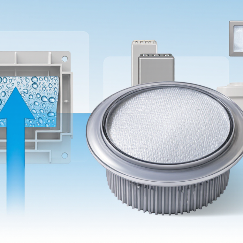
A hydrophobic vent is a porous component designed to let air or other gases pass while resisting liquid water. Its membrane has water-repelling surfaces, so droplets tend to bead rather than enter the pores. The pores are small enough to resist liquid penetration under specified conditions, yet allow gas movement. In a sealed electronics enclosure, for example, a vent can help air move in and out as temperatures change. That movement can reduce pressure differences that might stress seals. It is not a pump.
The membrane’s performance depends on its material, pore structure, exposed area, and installation. Water resistance also has limits: pressure, prolonged immersion, oils, or damaged seals can affect results. A vent rated for splashes should not automatically be treated as suitable for submersion. Details matter. Dust and other particles may be reduced, but a hydrophobic vent is not necessarily a sterile filter or a complete barrier to every contaminant. Engineers typically check airflow, water-entry pressure, and compatibility with the surrounding environment. Even a well-chosen membrane can underperform if adhesive edges are uneven or the housing traps water. That last detail is easy to overlook. A vent manages gas exchange; it does not make an enclosure invulnerable.
Hydrophobic vent membranes let air and other gases pass while resisting liquid water. Expanded PTFE is common because its interconnected pores create a large gas-flow area. Polypropylene is another option, especially where chemical compatibility or cost shapes the design. Published membrane specifications often place vent pore sizes around 0.1–1.0 μm, though the exact range varies by application. Smaller pores can raise water-entry pressure, but they may also restrict airflow. That trade-off matters.
A membrane is rarely just a thin film. Designers may laminate it to a support layer, then bond it into a vent housing. The support helps resist handling and pressure changes; the seal prevents liquid from bypassing the membrane at its edge. ASTM F316-03(2019) describes bubble-point and mean-flow-pore tests for characterizing membrane pore sizes. These measurements are more useful than visual inspection, but they do not predict every installed vent’s performance. Real results also depend on membrane area, assembly quality, and exposure to oils or surfactants. A specification can look reassuring on paper. I would still test the finished part under its actual pressure and fluid conditions.
A hydrophobic vent lets air pass through a porous membrane while resisting liquid water. Its tiny pores are treated to have low affinity for water. Air can move through these openings as pressure changes inside an enclosure. Water molecules, however, tend to form droplets rather than spread across the membrane. The surface tension of each droplet helps keep it from entering the pores. That is the basic idea.
Picture a sealed outdoor sensor warming in the sun. The air inside expands, then escapes through the vent instead of stressing the housing. When the temperature falls, air can move back in. Rain may bead on the membrane and run away.
Small details matter: pore size, membrane condition, and water pressure all affect performance. A strong spray or prolonged exposure may exceed the vent’s resistance. Oils, dust, or cleaning residue can also change how water behaves on the surface.
So “water-repellent” is not the same as invulnerable. It is worth checking the vent’s rated conditions and keeping its exposed face clear. The neat diagram can make this sound simpler than real use; installation and wear deserve attention too.
Hydrophobic vents are used in sealed electronic enclosures that face changing temperatures or air pressure. A breathable membrane lets air pass while resisting liquid water, helping reduce pressure differences that can strain seals. Consider an outdoor sensor warming in morning sunlight: air inside expands, then contracts as the unit cools. A vent can ease that cycle without leaving a wide opening.
In lighting housings, handheld instruments, and control boxes, vents can also limit moisture buildup. They are useful where rain, splashes, or damp air are expected, but they do not make every enclosure waterproof. Performance depends on membrane properties, vent placement, and the pressure pushing water against it. Small details matter. A blocked membrane, damaged gasket, or poorly fitted vent can undermine protection.
Equipment makers may choose different vent designs for dust exposure, airflow needs, cleaning methods, and expected service life. Some devices also need sound to pass through, so the membrane must balance acoustic performance with water resistance. That trade-off is not always neat. Engineers should test the assembled device under realistic conditions, rather than relying on the vent specification alone. A vent can help manage moisture, but it cannot correct a bad seal or careless installation.
Hydrophobic vents allow gas to pass through a water-repellent, porous membrane while resisting liquid water. They are commonly used to equalize pressure in sealed enclosures, sensors, lighting equipment, and battery housings.
How to read this chart: The bars show idealized water-entry pressure calculated for cylindrical pores using water surface tension of 0.0728 N/m and a water contact angle of 110°. Smaller pores produce higher theoretical entry pressure. Actual vent performance varies with membrane structure, surface treatment, and operating conditions.
What Is a Hydrophobic Vent and How Does It Work?
Factors That Affect Vent Performance and Durability
A hydrophobic vent lets air and pressure pass while resisting liquid water. Its microporous membrane works because water does not readily wet the pore surfaces. Performance depends on pore size, membrane chemistry, and the pressure pushing liquid toward the vent. Larger pores generally allow easier airflow, but reduce the pressure needed for water to enter. ASTM F316 describes bubble-point testing, which helps assess a membrane’s largest connected pores. It does not, by itself, prove long-term durability.
Surface condition matters, too. Dust, oil, cleaning residues, or skin oils can alter how water interacts with the membrane. At 20°C, water’s surface tension is about 72.8 mN/m, according to NIST reference data; temperature changes can shift this value and affect liquid-entry behavior. Heat, ultraviolet exposure, and repeated pressure cycles may also age the membrane or its seal. The seal is easy to overlook. A strong membrane can still leak if installation leaves a gap. Testing should reflect the real environment, including water pressure, temperature swings, and contamination. ASTM F316 can inform pore-size checks, while application-specific aging tests are still needed. I would not treat a single clean-water test as a durability verdict.
A hydrophobic vent is a gas-permeable, liquid-repellent membrane, commonly made from microporous materials such as expanded PTFE, polypropylene, or polyethylene. It allows air and other gases to pass while resisting liquid water, provided the liquid pressure stays below the membrane’s liquid-entry pressure. Actual performance depends on the membrane design and test conditions.
| Factor | What It Means | Effect on Vent Performance | Relevant Data or Relationship | Practical Considerations for Durability |
|---|---|---|---|---|
| Surface hydrophobicity | The membrane surface repels water because water does not readily spread across it. | Greater water repellency generally helps prevent liquid from entering the pores. | A water contact angle above 90° is commonly described as hydrophobic. Contact angle alone does not specify the vent’s allowable water pressure. | Oil, surfactants, or other surface-active substances can reduce repellency or alter wetting behavior. |
| Pore size and liquid-entry pressure | Microscopic pores allow gas flow while capillary forces resist liquid penetration. | Smaller pores generally increase resistance to liquid entry, but can also increase airflow resistance. | For an ideal cylindrical pore, liquid-entry pressure is proportional to 2γ|cosθ|/r, where γ is liquid surface tension, θ is contact angle, and r is pore radius. Real membranes have a distribution of pore sizes and more complex pore shapes. | Choose a vent with a liquid-entry-pressure rating suited to the maximum pressure, fluid, and exposure conditions of the application. |
| Liquid surface tension | Surface tension affects how strongly a liquid resists entering a small pore. | Liquids with lower surface tension can wet hydrophobic pores more readily and may penetrate at lower pressure than water. | At about 20°C, pure water has a surface tension of roughly 72 mN/m; isopropyl alcohol is roughly 22 mN/m. Mixtures and additives can have different values. | Test with the actual liquid, including cleaners, fuels, oils, or surfactant-containing solutions—not water alone. |
| Pressure difference | The pressure difference across the membrane, such as during filling, cooling, altitude changes, or squeezing. | Higher pressure can increase gas flow, but liquid may cross the membrane if the liquid-entry pressure is exceeded. | Liquid resistance is specified for a particular membrane and test method; there is no single pressure limit that applies to all hydrophobic vents. | Account for short pressure spikes as well as steady operating pressure, and avoid covering or mechanically loading the vent opening. |
| Membrane area and thickness | The exposed area and the distance gas must travel through the membrane. | A larger effective area generally supports greater airflow; a thicker or more obstructed path can increase flow resistance. | Airflow is normally reported at a stated pressure difference, for example in mL/min or L/min at a specified pressure. Values from different test conditions are not directly comparable. | Keep the active membrane area clear. Housing geometry, adhesive, and protective layers can reduce the usable area. |
| Temperature | Operating and storage temperatures affect the membrane, housing, seal, and any adhesive. | Temperature can change gas flow and material properties; condensation can temporarily obstruct pores. | Temperature limits are material- and assembly-specific and should be taken from the applicable product specification rather than assumed from the membrane material alone. | Check both continuous and peak temperatures, thermal cycling, and the possibility of hot or cold condensation. |
| Chemical exposure | Contact with chemicals may affect the membrane surface, support layers, housing, or bond. | Some substances can swell, weaken, contaminate, or wet components, reducing airflow or liquid resistance. | Chemical compatibility depends on the chemical, concentration, temperature, exposure duration, and the complete vent construction. | Validate compatibility under realistic exposure conditions, including cleaning agents and process residues. |
| Dust, particles, and biological fouling | Airborne particles or deposits can accumulate on or within the vent. | Blockage reduces effective area and can slow pressure equalization; surface deposits may also change wetting behavior. | Airflow can decline as the open membrane area becomes obstructed; the rate depends on particle size, concentration, and exposure. | Use a suitable location or protective design, and inspect or replace vents when contamination cannot be removed safely. |
| Condensation and humidity | Moist air can form liquid water when the vent or enclosure surface falls below the air’s dew point. | Water droplets may temporarily restrict gas flow even if the membrane resists liquid penetration. | Condensation occurs when a surface temperature is below the dew point of the surrounding air; the outcome depends on humidity and temperature cycling. | Consider enclosure orientation, drainage, thermal cycles, and whether the vent can dry between wetting events. |
| Mechanical damage and installation | Compression, abrasion, punctures, poor sealing, or incorrect mounting can compromise the vent assembly. | A damaged membrane or bypass leak can allow liquid or contaminants to enter, regardless of the membrane’s nominal properties. | Performance applies to the tested assembly and installation method; the membrane rating alone does not guarantee enclosure-level protection. | Follow mounting and sealing instructions, protect the membrane from sharp edges, and inspect the bond and housing after installation. |
| UV exposure and aging | Sunlight and long-term environmental exposure can degrade some polymers, seals, or adhesives. | Aging may change mechanical strength, bonding, or surface performance, depending on the materials used. | UV resistance and service life are construction- and exposure-specific; accelerated aging results do not automatically equal field life. | For outdoor use, verify UV and weathering suitability for the complete vent and follow the specified inspection or replacement schedule. |