#4 – 20133 102nd Avenue, Langley, B.C. V1M 4B4 Canada

#4 – 20133 102nd Avenue, Langley, B.C. V1M 4B4 Canada
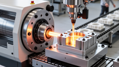
Injection molding is a high-volume manufacturing process that creates plastic parts with remarkable consistency. It begins when small polymer pellets enter a heated barrel. A rotating screw melts and blends them. Pressure then pushes the material into a shaped mold cavity. After cooling, the mold opens, and ejector pins release the finished component.
The sequence looks simple. It is not. Temperature, pressure, cooling time, and material moisture all influence the result. A slight imbalance can produce warpage, sink marks, short shots, or visible weld lines. John P. Beaumont, a respected injection molding engineer and author, stated, “Injection molding is a science, not an art.” That principle remains practical on the factory floor. Engineers measure melt temperature, cavity pressure, cycle time, and part dimensions before approving production.
This guide explains injection molding from material selection through mold design and quality inspection. You will see how the screw, nozzle, gate, runner, and cooling channels work together. You will also learn why a perfect-looking mold may still produce inconsistent parts. Real production is rarely flawless. Resin batches vary. Machines drift. Operators make adjustments. Even experienced teams sometimes overlook a small vent or an uneven cooling circuit. Careful testing exposes those weaknesses early. Reliable results come from documented settings, repeatable measurements, and honest review of failures. The goal is not merely to make one acceptable part. It is to build a stable process that delivers thousands of usable parts safely and efficiently.
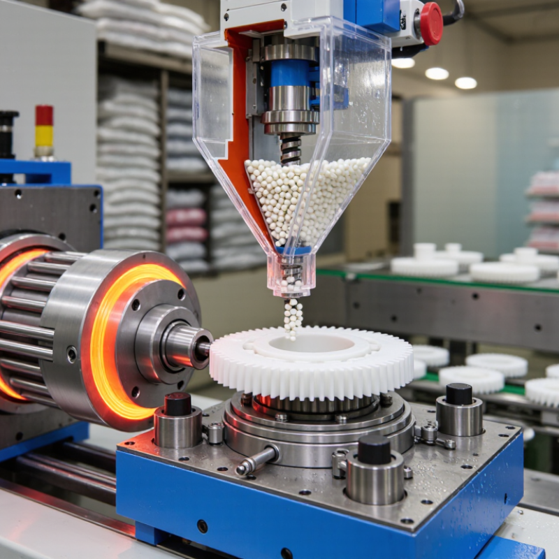
Injection molding is a manufacturing process that shapes heated material inside a mold. It is widely used because it can produce consistent parts in large quantities. The process usually begins with plastic pellets. A heated barrel melts them, while a screw pushes the material into a closed mold. The mold controls the part’s shape, surface texture, and dimensions. After cooling, the mold opens and releases the finished component. That cycle repeats.
Injection molding is useful for products that need repeatable quality, such as housings, caps, clips, medical components, and vehicle interiors. Once the mold is properly designed, each cycle can be fast and economical. It also creates complex shapes with holes, ribs, and snap-fit features. Less assembly may be needed. This saves labor and reduces handling. Different polymers can provide strength, flexibility, chemical resistance, or a smooth appearance.
The method is not perfect. Mold tooling can be costly, especially when the design changes late. A small error in wall thickness may cause warping, sink marks, or uneven cooling. This detail is easy to underestimate. Experienced engineers review material flow, cooling channels, draft angles, and expected shrinkage before production. During manufacturing, technicians monitor pressure, temperature, cycle time, and part dimensions. Reliable records support quality decisions, although real production still requires judgment. A mold may work well in testing and behave differently at full speed.
| Data Dimension | Key Information | Typical Details or Examples | Why It Matters |
|---|---|---|---|
| Definition | Injection molding is a manufacturing process in which molten material is injected into a mold cavity, cooled or cured, and then ejected as a formed part. | It is widely used for producing repeatable plastic components with defined shapes and dimensions. | The process combines material shaping, cooling, and part release in a controlled production cycle. |
| Main Process Sequence | Clamping, injection, packing and holding, cooling, mold opening, and ejection. | The machine closes and locks the mold, fills the cavity with material, maintains pressure, allows the part to solidify, and removes the finished component. | Each stage affects part quality, cycle time, dimensional accuracy, and material usage. |
| Clamping Unit | The clamping unit holds the mold halves together during injection and cooling. | It must provide enough force to resist the pressure that would otherwise open the mold and create flash. | Insufficient clamping force can cause unwanted material at the parting line, while excessive force may increase mold wear. |
| Injection Unit | The injection unit melts, meters, and pushes the molding material into the mold cavity. | Common components include a hopper, heated barrel, reciprocating screw, nozzle, and drive system. | Stable temperature, screw movement, and injection pressure help achieve consistent filling and part weight. |
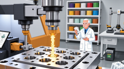
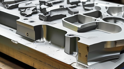
| Mold Structure | A mold normally contains two primary halves: the fixed half and the moving half. | Typical features include the sprue, runners, gates, cavity, core, cooling channels, vents, and ejector system. | Mold design controls material flow, cooling behavior, surface appearance, and ease of part removal. |
| Common Thermoplastics | Thermoplastics soften when heated and solidify when cooled, allowing them to be remelted under suitable conditions. | Examples include polyethylene, polypropylene, polystyrene, ABS, polyamide, polycarbonate, and polyoxymethylene. | Material selection depends on strength, stiffness, chemical resistance, temperature capability, appearance, and cost. |
| Other Moldable Materials | Injection molding can also process selected thermosets, elastomers, and liquid silicone materials. | These materials may require curing or cross-linking rather than simple cooling to reach their final properties. | The material family determines machine configuration, mold temperature, cycle conditions, and post-processing requirements. |
| Injection Stage | The screw moves forward and forces the molten material through the nozzle, runner system, and gate into the cavity. | Injection speed and pressure are adjusted according to the material, mold geometry, wall thickness, and flow length. | Correct filling conditions reduce short shots, weld lines, burn marks, and excessive shear-related defects. |
| Packing and Holding | Additional pressure is applied after the cavity is nearly full to compensate for material shrinkage during cooling. | The holding phase may continue until the gate freezes or the required part weight is reached. | Appropriate holding pressure improves dimensional stability and reduces sink marks, but excessive pressure can cause flash or internal stress. |
| Cooling and Solidification | Heat is removed through cooling channels in the mold until the part is sufficiently rigid for ejection. | Cooling time is influenced by material properties, wall thickness, mold temperature, and cooling-channel layout. | Cooling often represents a significant portion of the cycle and strongly affects productivity and warpage. |
| Cycle Time | The complete cycle includes mold closing, injection, holding, cooling, mold opening, and ejection. | Thin-walled parts may have short cycles, while thick or highly engineered parts generally require longer cooling periods. | Shorter stable cycles increase output, but reducing cooling or filling time too far can create defects. |
| Part Design Guidelines | Uniform wall thickness, suitable draft angles, rounded corners, ribs, bosses, and correctly positioned gates support reliable molding. | Sudden thickness changes should be minimized, and features should allow the part to release from the mold without damage. | Designing for manufacturability can reduce sink marks, warpage, tooling complexity, and production cost. |
| Typical Applications | Injection molding is used for high-volume production of technical and consumer parts. | Applications include housings, caps, closures, containers, automotive interior components, electrical enclosures, medical components, and appliance parts. | The process is suitable when consistent dimensions, repeatability, and efficient production are important. |
| Production Volume | The process is especially economical for medium- to high-volume production after the mold has been made. | A single mold can contain one cavity or multiple cavities to produce several parts per machine cycle. | Tooling costs are spread across more parts as production volume increases, lowering the average part cost. |
| Dimensional Repeatability | Repeatability depends on mold accuracy, machine control, material consistency, cooling uniformity, and process stability. | Parts produced under stable conditions can maintain closely controlled dimensions, although tolerances vary by material and design. | Repeatable processing is important for assemblies, moving components, seals, and interchangeable parts. |
| Surface Finish | The molded surface generally reproduces the texture and finish of the corresponding mold surface. | Finishes may range from glossy or polished surfaces to textured or matte surfaces. | Surface texture affects appearance, friction, grip, defect visibility, and mold release behavior. |
| Material Efficiency | Injection molding can produce near-net-shape parts with relatively little material waste. | Runners and sprues may be reground when the material and product requirements permit; hot-runner systems can reduce runner waste. | Efficient material use can lower costs, but recycled content and regrind must be controlled to maintain performance. |
| Primary Advantages | High repeatability, fast cycle times, complex geometries, multiple surface finishes, and compatibility with automation. | Insert molding, overmolding, multi-cavity tooling, and automated part handling can expand production capabilities. | These advantages make the process suitable for consistent, scalable manufacturing. |
| Primary Limitations | Initial tooling costs can be substantial, and design changes may be difficult after the mold is completed. | Potential issues include warpage, sink marks, weld lines, short shots, flash, burn marks, and material degradation. | Early design review and process trials help manage tooling risk and avoid costly production changes. |
| Quality Control Checks | Quality control may include visual inspection, dimensional measurement, weight checks, functional testing, and material verification. | Process records can include melt temperature, mold temperature, injection pressure, holding pressure, cycle time, and cooling time. | Monitoring both part characteristics and process conditions helps identify variation before it affects large quantities. |
| Sustainability Considerations | Energy use, material selection, mold life, scrap rate, recycled content, and product durability influence overall environmental impact. | Lightweight designs, efficient heating and cooling, optimized cycles, and appropriate recycling practices can reduce resource consumption. | Sustainability performance depends on the complete product life cycle rather than on the molding step alone. |
Note: Actual processing temperatures, pressures, cycle times, tolerances, and material behavior vary according to the selected material, part geometry, mold design, machine capacity, and required product performance.
What Is Injection Molding and How Does It Work?
Injection molding turns heated material into precise, repeatable parts. Common materials include polypropylene, ABS, nylon, polycarbonate, and thermoplastic elastomers. Each behaves differently during melting, filling, cooling, and shrinkage. Material choice depends on strength, flexibility, temperature resistance, appearance, and production volume.
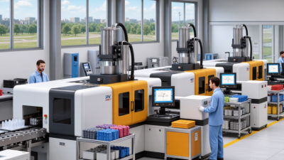
An injection molding machine has four working areas: the hopper, heated barrel, injection unit, and clamping unit. Pellets enter the hopper and move through a rotating screw. The screw melts and pushes the material into a closed mold. The mold contains a cavity and core, which create the part’s external and internal shapes. Other key components include the sprue, runners, gates, cooling channels, and ejector pins. Clamping force must resist injection pressure. Otherwise, unwanted flash may appear along the parting line.
Tips: Check material drying requirements before processing nylon or polycarbonate. Keep gates balanced when designing multi-cavity molds. Inspect cooling channels regularly, because poor cooling can cause warping. In practice, no setup is perfect. A small temperature change may alter surface finish, cycle time, or dimensions. Even experienced technicians must compare trial parts with measured data. A mold can look well designed but still reveal filling problems during production. That is where careful observation matters.
What Is Injection Molding and How Does It Work?
How the Injection Molding Process Works Step by Step
Injection molding begins with material preparation. Plastic pellets are dried when moisture could damage the part. The pellets enter a heated barrel, where rotating screws melt and mix them. Temperatures commonly range from 180°C to 350°C, depending on the polymer. The screw then pushes a measured shot toward the mold.
The mold closes under high clamping force. Molten plastic enters through the sprue, runners, and gate, filling the cavity under controlled pressure. Sensors can track pressure, temperature, and filling time. This matters because small changes may create warpage, sink marks, or short shots. PlasticsEurope reported global plastics production at 400.3 million tonnes in 2022, showing the scale of material processing behind everyday products.
After filling, the machine applies holding pressure while the gate begins to freeze. Cooling follows. Water channels inside the mold remove heat, but uneven cooling can still distort thin walls. The mold opens, and ejector pins release the finished part. Operators then inspect dimensions, surface quality, and weight before repeating the cycle.
It looks simple.
In practice, the first trial rarely behaves perfectly. A technically correct setting may still waste material if cooling is uneven. The 2024 SPI Moldmaking Industry Report highlights continuing pressure for tighter quality control and shorter production cycles. Engineers often adjust injection speed, holding pressure, and cooling time through several trials. That practical feedback remains essential, because simulation cannot fully reproduce every mold, resin, and factory condition.
Injection molding melts thermoplastic material, injects it into a closed mold, packs the cavity, cools the part, and then ejects the finished product. The chart shows a representative 30-second cycle for a small-to-medium molded component.
Cooling commonly takes the largest share of the cycle because the molded part must solidify sufficiently before ejection. Actual timing varies with material, part thickness, mold design, and machine settings.
Injection molding turns heated plastic into precise parts through a mold cavity. The machine injects material under pressure, holds it briefly, then cools and ejects the part. However, part quality depends heavily on design decisions made before production begins.
Wall thickness should remain as uniform as possible. Sudden changes can cause sink marks, warping, or internal stress. Ribs add strength, but their thickness should usually stay below the main wall thickness. Draft angles help parts release cleanly from the mold. Without enough draft, ejector pins may leave marks or damage edges. Rounded corners also improve material flow and reduce stress. Sharp corners are rarely helpful.
Tips: Place gates where flow can fill the cavity evenly. Keep weld lines away from high-load areas. Add vents near the end of the flow path to release trapped air. Check tolerances against the material’s expected shrinkage. Small details matter.
Temperature, pressure, cooling time, and mold alignment also affect results. A skilled designer reviews these factors together, not separately. In practice, even a well-planned part may need adjustment after trial molding. A rib may be too strong. A gate may leave an unwanted mark. That is normal, but it should not be ignored. Test samples, measure critical features, and compare them with the drawing before approving full production. Reliable quality comes from controlled iteration, clear specifications, and honest review of defects.
Injection molding produces plastic parts by forcing molten material into a shaped mold. Small pellets enter a heated barrel and soften under controlled temperature. A screw then pushes the material into the closed mold. After cooling, the mold opens and ejector pins release the finished part. This cycle may take seconds, depending on part size, material, and wall thickness.
Common applications include automotive clips, appliance housings, medical device components, packaging caps, and electronic enclosures. The process offers excellent repeatability, smooth surfaces, and efficient high-volume production. It can also create ribs, snap fits, and other detailed features in one part.
However, the mold may require substantial upfront investment. Design changes become expensive after tooling begins. Uneven cooling can cause warping, sink marks, or visible flow lines. Some shapes still need secondary assembly or finishing. These limits are easy to underestimate.
Tips:
Check wall thickness early. Add draft angles to support clean ejection. Test the gate location before final tooling. A prototype can reveal problems that drawings miss. In practice, small design compromises often improve reliability. Injection molding is efficient, but not automatically economical for short production runs. Material selection also matters. Heat, moisture, chemical exposure, and repeated stress can change performance over time. A qualified engineer should review tolerances and testing needs before production.