#4 – 20133 102nd Avenue, Langley, B.C. V1M 4B4 Canada

#4 – 20133 102nd Avenue, Langley, B.C. V1M 4B4 Canada
In 2026, strong injection molding design begins long before a tool reaches the press. A thin wall, a sharp corner, or a misplaced gate can affect cycle time, appearance, and part strength. These choices matter. Yet design advice is useful only when it accounts for the resin, the mold, and the part’s intended job. An enclosure for a handheld device, for example, may need snap fits, clean surfaces, and consistent wall thickness without becoming bulky.
This guide examines practical decisions that can improve moldability and part performance. It covers uniform walls, draft angles, ribs, bosses, gate placement, and tolerances, connecting each choice to likely production outcomes. It also considers simulation and design reviews, which can reveal trapped air, sink marks, or difficult ejection before production begins. No tool replaces judgment. Material data and supplier feedback still matter, especially when recycled content, cosmetic requirements, or tight schedules enter the brief. Small details matter. Some recommendations will not fit every project; that is the point. A rib that improves stiffness in one housing may create a visible sink in another. Treat these tips as questions to test, not rules to copy. Careful review can reduce costly tool changes, though even a well-planned design may need adjustment once the first molded parts are inspected.
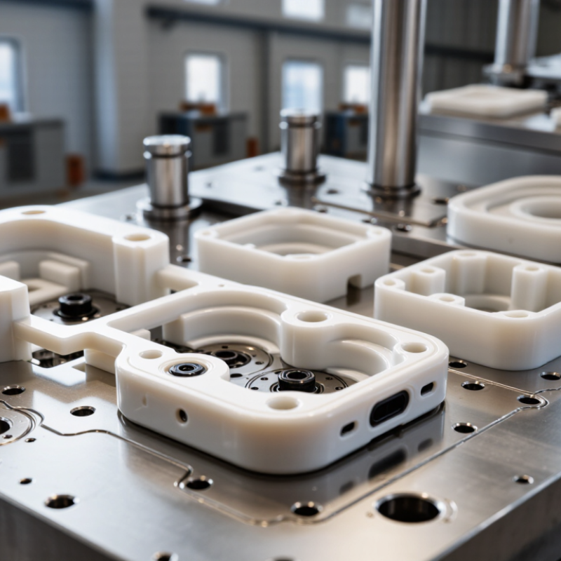
Core injection molding design in 2026 still begins with the part, not the machine. Aim for consistent wall thickness so plastic cools at a similar rate across the component. Thick intersections can hold heat, creating sink marks or internal stress. Small changes matter. Use ribs to add stiffness instead of making the whole wall thicker. Keep ribs slightly thinner than the adjoining wall, and check their spacing against the material and part geometry.
Add draft to vertical faces so the part releases without scuffing or excessive force. Even a modest angle can help, though textured surfaces may need more. Place gates where flow can reach the part evenly, and avoid putting them on highly visible surfaces when appearance matters. Vents also need attention: trapped air near the end of fill can burn or weaken a feature. These details depend on the mold, resin, and production conditions, so generic rules are starting points, not guarantees.
Review likely shrinkage and warpage before tooling. Simulation can flag uneven filling or cooling, but it cannot replace a physical trial. Check critical dimensions on molded samples, especially around ribs, holes, and broad flat panels. A design may look clean in CAD and still distort after ejection. That is frustrating, but useful feedback. Adjust one variable at a time where possible, document the result, and confirm the revised part under realistic cycle conditions.
Choose resin by function, not habit. Check impact strength, heat exposure, chemical contact, color, and expected production volume. A recycled grade may suit a noncritical housing, but test its flow and mechanical properties before locking the design. The OECD’s 2022 Global Plastics Outlook reports that only 9% of plastic waste was recycled in 2019. That figure makes recyclability worth considering, but it does not replace part-performance testing.
For many small-to-medium parts, 1.5–3 mm walls are a practical starting point, not a fixed rule. Resin, flow length, and part geometry all matter. Keep walls as even as possible; a thick boss beside a thin panel can cool unevenly and cause sink marks or warping. A neat CAD model can still hide these risks. Check the tool layout and resin data before approving the part.
Tips: Add ribs instead of bulky walls for stiffness. Use generous inside corners to help resin flow. Keep ribs thinner than the main wall, then review a filled-part simulation or molding trial. One trade-off remains: thinner walls save material, but may demand tighter process control.
For 2026, design the part around the way plastic flows and cools, not just its final shape. The Society of Plastics Engineers’ injection-molding design guidance commonly recommends about 1–2 degrees of draft on vertical faces. That small angle helps a warm part release without scuffing. Add more draft to deep, textured walls. A smooth-looking CAD model can still stick in a real tool.
Ribs add stiffness, but thick ribs often create sink marks on the opposite surface. Industry design guides generally place rib thickness at roughly 50–60% of the adjoining wall; keep ribs low and spaced where possible. Bosses need similar restraint. A boss wall near 60% of nominal wall thickness can reduce local mass, while a supporting rib may connect it to the part without creating a heavy solid lump. Keep the core pin accessible for cooling and ejection. Test the actual resin and geometry: these ratios are starting points, not laws. I would still challenge a tidy rule if the first molded samples show warpage. Tiny details matter.
Gate, runner, and cooling choices shape fill quality, cycle time, and part appearance. Place the gate where flow can reach the thickest sections without trapping air near ribs or corners. Keep the gate away from visible surfaces when appearance matters. A fan gate can spread flow across a wide edge, while a pin gate may suit a compact part. Each option leaves a different witness mark. Test the actual resin and geometry before fixing the location.
Runner layouts should deliver melt to each cavity with similar pressure and temperature. For a multi-cavity tool, compare runner lengths and branch dimensions rather than relying on symmetry alone. A balanced drawing can still fill unevenly. Mold-flow analysis can flag pressure loss and likely weld lines, but a molding trial remains important. Check short shots, part weight, and fill time; small differences can reveal a poor balance.
Cooling deserves equal attention. Keep channels close enough to remove heat evenly, but leave sufficient steel around cores and cavities. Use baffles or bubblers where straight channels cannot reach deep features. Avoid sharp changes in cooling distance, which can leave one surface glossy and another warped. Measure temperatures at several points during trials. A neat channel layout is not automatically an effective one, and complex cooling may be harder to maintain. Revisit the design when cycle data disagrees with simulation.
Typical starting-point ratios for early part and mold design. Each bar shows a recommended range.
Gate thickness is commonly designed at about 50–80% of nominal part-wall thickness, while gate width is often 100–150% of gate thickness. For cooling, a channel centerline is commonly placed 1.5–2 times the channel diameter from the molding surface, with channel spacing around 2.5–3 times the diameter. Use balanced runners and validate dimensions with resin-specific flow and cooling analysis; these are rules of thumb, not universal specifications.
A design is not validated because it looks clean in CAD. Check whether resin can fill the part evenly, cool predictably, and release without damage. Flow simulation can flag thin ribs, trapped air, and weld lines before tooling begins. Then review the results with a molder; simulation is useful, but it is not the machine.
Small details matter. Measure wall thickness around bosses and corners, where uneven cooling can cause sink marks or warping. Build trial parts and inspect critical dimensions with gauges or a coordinate-measuring machine. Test fit, load, and repeated assembly under realistic conditions. Record the resin lot, machine settings, and defects for each run. I have seen teams overlook a tight tolerance until assembly. That delay is frustrating.
Validate cost and sustainability together. Compare cycle time, material use, scrap rate, and expected tool maintenance—not just the quoted part price. A lighter design may reduce material, but fragile features can increase rejects. Where recycled resin is considered, confirm its flow and mechanical properties through trials. Track energy per production cycle if sustainability is a target. The first test may fail. That is useful data, though teams sometimes move on too quickly. Keep the failure notes, revise one variable at a time, and repeat the measurement.
| Design Area | Practical Design Guidance | Quality Validation | Cost Validation | Sustainability Validation |
|---|---|---|---|---|
| Wall thickness | Keep walls as uniform as the part’s function allows. Avoid abrupt thickness changes; use gradual transitions. Many thermoplastic parts use nominal walls around 1–4 mm, but the suitable value depends on resin, flow length, and part geometry. | Review mold-flow results for short shots, sink marks, air traps, and uneven filling. Inspect molded samples at thick-to-thin transitions. | Compare material volume and cycle time across wall-thickness options. Thicker sections generally require more material and cooling time. | Reduce unnecessary material while confirming that thinner walls still meet strength, impact, and service-life requirements. |
| Draft and ejection | Provide draft on walls parallel to the mold-opening direction. About 1–2 degrees per side is a common starting point for smooth surfaces; textured or deep features may need more. | Check for drag marks, scuffing, deformation, and sticking during ejection. Confirm draft direction against the parting line and surface texture. | Validate that the draft and ejection layout avoid added actions, manual removal, or unnecessarily complex tooling. | Reliable ejection can reduce rejected parts and rework. Avoid adding excessive material solely to compensate for poor release geometry. |
| Ribs and bosses | As a common starting point, rib thickness is about 40–60% of the adjoining nominal wall. Use gradual rib-to-wall transitions and avoid thick intersections. Size bosses to suit fastening loads and molding conditions. | Inspect rib roots and boss bases for sink, voids, cracking, and warpage. Test assembled parts under representative fastening loads. | Compare ribbed designs with solid sections; ribs can add stiffness with less material when properly proportioned. | Use geometry to achieve required stiffness rather than increasing overall wall thickness. Confirm that material savings do not reduce durability. |
| Corners and transitions | Use radii at internal and external corners where functional requirements permit. Smooth transitions help reduce stress concentration and support more consistent filling. | Evaluate stress concentrations with analysis or physical testing. Check corners for cracks, incomplete filling, and localized sink. | Review whether radii simplify machining and reduce the risk of difficult-to-correct tool details. | Longer-lasting parts can reduce replacement demand. Keep radii compatible with fit, sealing, and assembly needs. |
| Gates and flow paths | Choose gate locations to support balanced filling, suitable weld-line placement, and acceptable appearance. Keep flow paths practical and account for inserts, ribs, and changes in wall thickness. | Use mold-flow analysis to review fill balance, pressure, weld lines, air traps, and fiber orientation where relevant. Confirm results with trial molding. | Compare gate options for tool complexity, runner material, cycle time, and expected scrap. Validate the selected system with the mold design. | Assess runner and purge waste. Where appropriate, evaluate hot-runner systems or regrind use against energy, quality, and material-control requirements. |
| Tolerances and shrinkage | Apply tighter tolerances only to function-critical features. Shrinkage varies by resin grade, additives, flow direction, and processing conditions; use current supplier data and tool-specific experience. | Define a measurement plan for critical dimensions and verify capability using parts produced under stable, documented process conditions. | Compare the cost of tighter tolerances with assembly and performance requirements. Avoid specifying precision that does not provide a functional benefit. | Stable dimensions can reduce rejects and rework. Validate any material change for its effect on shrinkage and dimensional consistency. |
| Cooling and warpage | Design for balanced cooling and avoid large variations in section thickness. Locate cooling channels to support uniform heat removal while maintaining tool strength and serviceability. | Review predicted temperature distribution and warpage, then measure molded parts after conditioning. Check flatness and fit in the intended assembly. | Assess cooling time as a major cycle-time factor. Compare tooling and cycle-time trade-offs before finalizing channel layouts. | Track energy use per accepted part where production data are available. Reducing cooling time is beneficial only if it does not increase defects or scrap. |
| Material selection and recycled content | Select a resin based on mechanical, thermal, chemical, regulatory, and processing requirements. For recycled or bio-based content, verify grade-specific properties and supply consistency. | Test representative samples for required performance, appearance, and dimensional stability. Revalidate changes in resin grade, colorant, or recycled-content level. | Compare total part cost, including material, cycle time, drying, quality controls, and supply risk—not resin price alone. | Document recycled or renewable content and evaluate product life, repairability, and end-of-life routes. Do not assume a material is recyclable in every local system. |
| Design verification and production trial | Set measurable acceptance criteria for dimensions, appearance, mechanical performance, and assembly before tool release. Include expected process and material variation in the review. | Validate with molded samples, dimensional inspection, functional tests, and a documented process window. Recheck critical features after design or material changes. | Compare predicted cycle time and yield with production-trial results. Use these results to update cost estimates before scaling production. | Record scrap, regrind, material use, and energy data per accepted part where feasible. Use the baseline to assess improvement opportunities. |
Guideline values are starting points, not universal specifications. Confirm final dimensions, tolerances, and processing conditions with the selected resin supplier, mold designer, and production trials.